How to Draw Class Diagram in Software Engineering

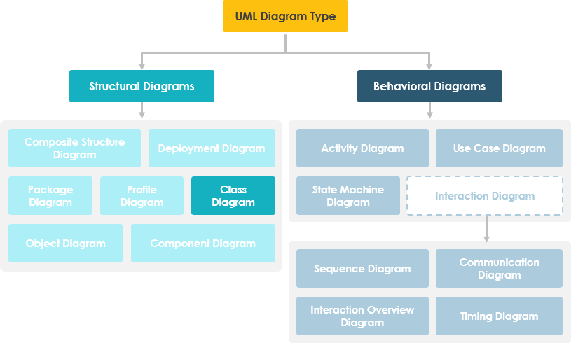
In software technology, a class diagram in the Unified Modeling Linguistic communication (UML) is a type of static structure diagram that describes the structure of a system by showing the organisation's classes, their attributes, operations (or methods), and the relationships amid objects.
Learn UML Faster, Improve and Easier
Are you looking for a Free UML tool for learning UML faster, easier and quicker? Visual Image Community Edition is a UML software that supports all UML diagram types. It is an international award-winning UML modeler, and even so information technology is easy-to-utilize, intuitive & completely free.
Free Download
Purpose of Form Diagrams
- Shows static structure of classifiers in a organisation
- Diagram provides a basic notation for other structure diagrams prescribed by UML
- Helpful for developers and other team members likewise
- Business Analysts can utilise class diagrams to model systems from a business concern perspective
A UML class diagram is made up of:
- A set of classes and
- A set up of relationships betwixt classes
What is a Class
A description of a group of objects all with like roles in the system, which consists of:
- Structural features (attributes) define what objects of the class "know"
- Represent the state of an object of the class
- Are descriptions of the structural or static features of a course
- Behavioral features (operations) ascertain what objects of the class "tin can do"
- Ascertain the fashion in which objects may interact
- Operations are descriptions of behavioral or dynamic features of a class
Class Notation
A class notation consists of 3 parts:
- Course Name
- The name of the grade appears in the beginning segmentation.
- Class Attributes
- Attributes are shown in the 2d partition.
- The attribute blazon is shown after the colon.
- Attributes map onto member variables (data members) in code.
- Class Operations (Methods)
- Operations are shown in the third partition. They are services the course provides.
- The return blazon of a method is shown after the colon at the end of the method signature.
- The return type of method parameters is shown after the colon following the parameter name.
- Operations map onto grade methods in lawmaking

The graphical representation of the grade - MyClass every bit shown above:
- MyClass has 3 attributes and 3 operations
- Parameter p3 of op2 is of type int
- op2 returns a float
- op3 returns a arrow (denoted by a *) to Class6
Course Relationships
A class may be involved in ane or more than relationships with other classes. A relationship can be i of the following types: (Refer to the figure on the right for the graphical representation of relationships).
| Human relationship Type | Graphical Representation |
|---|---|
| Inheritance (or Generalization):
| 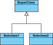 |
| Simple Association:
| 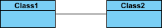 |
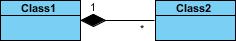
| Aggregation: A special blazon of association. It represents a "part of" relationship.
| 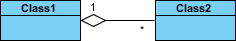 |
| Composition: A special type of aggregation where parts are destroyed when the whole is destroyed.
|  |
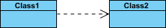
| Dependency:
|  |
Relationship Names
- Names of relationships are written in the middle of the association line.
- Adept relation names make sense when you read them out loud:
- "Every spreadsheet contains some number of cells",
- "an expression evaluates to a value"
- They often take a minor arrowhead to show the management in which management to read the relationship, eastward.g., expressions evaluate to values, only values do non evaluate to expressions.

Relationship - Roles
- A function is a directional purpose of an association.
- Roles are written at the ends of an association line and depict the purpose played by that class in the relationship.
- East.grand., A cell is related to an expression. The nature of the human relationship is that the expression is the formula of the prison cell.
Visibility of Class attributes and Operations
In object-oriented blueprint, there is a note of visibility for attributes and operations. UML identifies 4 types of visibility: public, protected, private, and package.
The +, -, # and ~ symbols before an aspect and operation name in a class denote the visibility of the attribute and functioning.
- + denotes public attributes or operations
- - denotes private attributes or operations
- # denotes protected attributes or operations
- ~ denotes packet attributes or operations
Class Visibility Example
In the example above:
Admission for each of these visibility types is shown below for members of different classes.
| Access Right | public (+) | individual (-) | protected (#) | Package (~) |
|---|---|---|---|---|
| Members of the same class | yes | yes | yeah | yes |
| Members of derived classes | yes | no | yes | yes |
| Members of whatever other grade | yes | no | no | in same packet |
Multiplicity
How many objects of each class take part in the relationships and multiplicity can be expressed as:
- Exactly one - 1
- Zero or one - 0..one
- Many - 0..* or *
- One or more - 1..*
- Exact Number - due east.g. 3..4 or vi
- Or a complex relationship - e.g. 0..1, 3..4, 6.* would mean whatever number of objects other than 2 or 5
Multiplicity Example
- Requirement: A Student can accept many Courses and many Students tin exist enrolled in one Form.
- In the example beneath, the class diagram (on the left), describes the statement of the requirement above for the static model while the object diagram (on the right) shows the snapshot (an instance of the class diagram) of the form enrollment for the courses Software Engineering and Database Management respectively)

Aggregation Example - Computer and parts
- An aggregation is a special case of association denoting a "consists-of" hierarchy
- The amass is the parent class, the components are the children classes

Inheritance Instance - Cell Taxonomy
- Inheritance is another special case of an clan denoting a "kind-of" hierarchy
- Inheritance simplifies the analysis model past introducing a taxonomy
- The child classes inherit the attributes and operations of the parent grade.

Class Diagram - Diagram Tool Example
A grade diagram may too have notes attached to classes or relationships. Notes are shown in grey.

In the instance above:
We can interpret the pregnant of the above grade diagram by reading through the points as following.
- Shape is an abstract class. It is shown in Italics.
- Shape is a superclass. Circle, Rectangle and Polygon are derived from Shape. In other words, a Circle is-a Shape. This is a generalization / inheritance human relationship.
- In that location is an association betwixt DialogBox and DataController.
- Shape is function-of Window. This is an aggregation relationship. Shape can exist without Window.
- Signal is part-of Circumvolve. This is a composition human relationship. Point cannot exist without a Circle.
- Window is dependent on Event. However, Consequence is non dependent on Window.
- The attributes of Circumvolve are radius and centre. This is an entity course.
- The method names of Circle are area(), circum(), setCenter() and setRadius().
- The parameter radius in Circle is an in parameter of type float.
- The method area() of class Circumvolve returns a value of type double.
- The attributes and method names of Rectangle are hidden. Some other classes in the diagram also take their attributes and method names hidden.
Dealing with Circuitous Organization - Multiple or Single Class Diagram?
Inevitably, if you lot are modeling a big organisation or a big business surface area, there volition be numerous entities you must consider. Should we use multiple or a single class diagram for modeling the trouble? The answer is:
- Instead of modeling every entity and its relationships on a single class diagram, it is meliorate to use multiple class diagrams.
- Dividing a system into multiple class diagrams makes the organization easier to understand, especially if each diagram is a graphical representation of a specific part of the system.
Perspectives of Class Diagram in Software Development Lifecycle
We tin use class diagrams in different evolution phases of a software development lifecycle and typically by modeling class diagrams in three different perspectives (levels of item) progressively equally we move frontward:
Conceptual perspective: The diagrams are interpreted as describing things in the real world. Thus, if you lot take the conceptual perspective you draw a diagram that represents the concepts in the domain under study. These concepts will naturally relate to the classes that implement them. The conceptual perspective is considered language-contained.
Specification perspective: The diagrams are interpreted as describing software abstractions or components with specifications and interfaces only with no commitment to a detail implementation. Thus, if y'all take the specification perspective nosotros are looking at the interfaces of the software, non the implementation.
Implementation perspective: The diagrams are interpreted as describing software implementations in a particular applied science and language. Thus, if you accept the implementation perspective we are looking at the software implementation.
Try to Draw UML Grade Diagram Now
You've learned what a Course Diagram is and how to describe a Course Diagram. Information technology's time to draw a Class Diagram of your own. Get Visual Paradigm Community Edition, a free UML software, and create your ain Course Diagram with the free Class Diagram tool. It'due south piece of cake-to-use and intuitive.
Gratis Download
Source: https://www.visual-paradigm.com/guide/uml-unified-modeling-language/what-is-class-diagram/
0 Response to "How to Draw Class Diagram in Software Engineering"
Post a Comment